The STM32F411CEU6 is a microcontroller based on the Arm® Cortex®-M4 32-bit core, running at speeds up to 100 MHz. It features a single-precision floating-point unit (FPU), digital signal processing (DSP) instructions, and a memory protection unit (MPU), offering a robust mix of performance and security. With up to 512 KB of Flash memory and 128 KB of SRAM, this device is ideal for complex embedded applications.
Belonging to ST’s Dynamic Efficiency line, the STM32F411CEU6 also includes an innovative Batch Acquisition Mode (BAM) for enhanced power savings. It supports a wide array of peripherals, including a 12-bit ADC, multiple timers, I2C, SPI, I2S (with audio-grade PLL support), USART, SDIO, and USB 2.0 OTG FS.
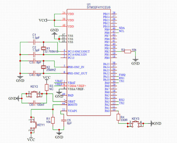
This schematic illustrates the minimal system design for the STM32F411CEU6 microcontroller, incorporating essential functional modules such as power supply, clock input, reset circuit, and user buttons. The chip connects to power and ground through multiple VDD and VSS pins, with a capacitor connected to the VCAP1 pin to stabilize the core voltage. The VBAT pin can be connected to a battery to supply power to the real-time clock (RTC), supporting low-power applications.
For the clock configuration, the system integrates two crystal oscillators: a 25MHz crystal connected to the PH0 and PH1 pins serves as the main system clock, and a 32.768kHz crystal connected to PC14 and PC15 is used for the RTC clock input. Additionally, the NRST pin is connected to a button and pull-up resistor to form a manual reset circuit, while the BOOT0 pin is grounded to enable booting from the main Flash memory.
In terms of button functionality, the circuit includes three buttons connected to PA0, PA1, and NRST, allowing user input or control. PA9 and PA10 serve as the TX1 and RX1 pins for UART communication, facilitating debugging and data exchange during development. Overall, the schematic provides a compact and practical layout, suitable as a core control board or base development platform for the STM32F411CEU6.
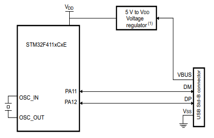
This diagram illustrates the basic connection block for STM32F411CEU6 in a USB application. The microcontroller uses an external crystal oscillator (connected to OSC_IN and OSC_OUT) to provide a stable clock source. For power supply, a 5V-to-VDD voltage regulator is used to power the VDD pin, which serves as the main supply for the chip.
In the USB interface section, PA11 and PA12 function as the USB DM (differential minus) and DP (differential plus) data lines, respectively, connected to a standard USB Type-B connector to enable full-speed USB communication. The VBUS pin is connected to the USB port to detect USB connection and power-on events, while the VSS pin is grounded to maintain system stability. This clear and concise block diagram is well-suited for designing USB communication applications based on the STM32F411.
| Parameter | Specification |
| Core | ARM® Cortex®-M4 (with FPU) |
| Core Size | 32-Bit Single-Core |
| Speed | 100MHz |
| Number of I/O | 36 |
| Program Memory Type | FLASH |
| Flash Memory | 512 KB |
| RAM Size | 128K x 8 |
| Operating Voltage | 1.7V ~ 3.6V |
| I/O Pins | 50 GPIOs |
| Data Converters | A/D 10x12b |
| External Oscillators | 32.768 kHz (LSE), 4 to 26 MHz (HSE) |
| Internal Oscillators | 16 MHz HSI, 32 kHz LSI, 48 MHz for USB |
| Operating Temperature Range | -40°C ~ 85°C |
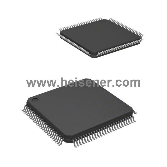
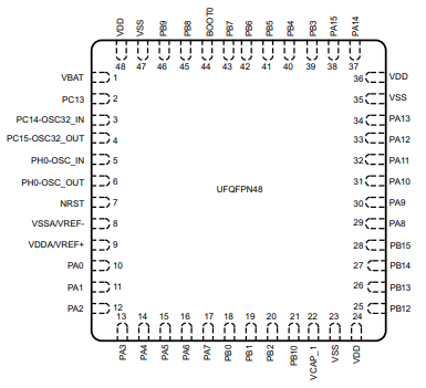
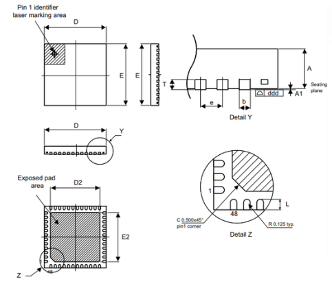
| Package Type | 48-UFQFPN (7x7) |
| USB Support | USB 2.0 Full Speed (PA11/PA12) |
Based on 32-bit ARM® Cortex®-M4 core.
Up to 512 KB Flash and 128 KB SRAM for code and data storage.
Offers low power modes with standby current as low as 1.8 µA.
Includes a high-speed 12-bit ADC with up to 16 input channels.
Supports up to 11 timers including PWM, watchdogs, and encoder inputs.
Equipped with up to 13 communication interfaces including USB 2.0 FS OTG.
Features 16-stream DMA controller with FIFO and burst mode.
Provides up to 81 GPIOs, with most supporting up to 5 V input tolerance.
Integrated RTC with calendar, subsecond accuracy, and VBAT backup support.
Motor drive and application control
Medical equipment
Industrial applications: PLC, inverters, circuit breakers
Printers, and scanners
Alarm systems, video intercom, and HVAC
Home audio appliances
Mobile phone sensor hub
STMicroelectronics is one of the world’s leading semiconductor manufacturers, headquartered in Geneva, Switzerland. It focuses on providing a wide range of semiconductor solutions that are extensively used in industries such as industrial automation, automotive, communications, and consumer electronics. As the developer of the STM32 series of microcontrollers, ST possesses strong technical expertise and innovative capabilities in embedded systems, analog technologies, and power management.
Datasheet PDF(https://dir.heisener.com/DatasheetDownload/STM32F411VET6U.pdf)
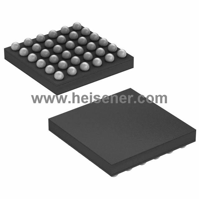
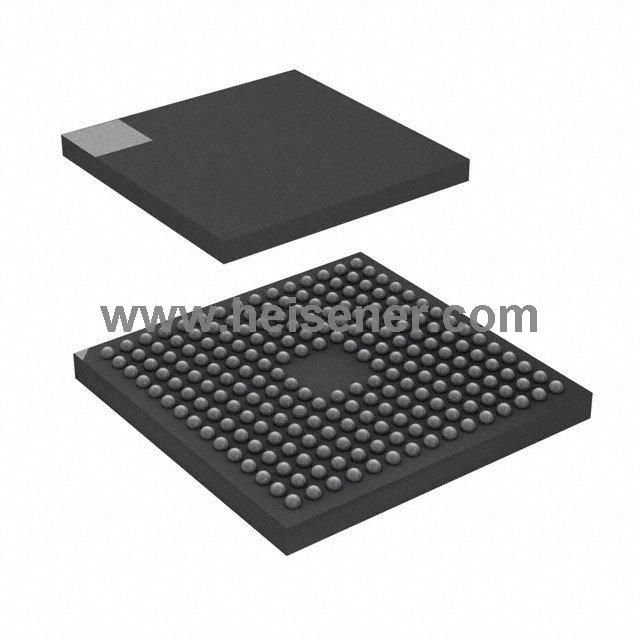
The STM32F411CEU6 comes in a 48-pin UFQFPN (Ultra Thin Fine Pitch Quad Flat Package) with a 7x7 mm footprint. This compact and low-profile package is designed to optimize board space while ensuring excellent thermal performance and ease of soldering.
Equivalent models for the STM32F411CEU6 include STM32F411RE, STM32F401CC, STM32F401RE, STM32F405RG, and STM32F415RG.
It is a 32-bit ARM Cortex-M4 microcontroller from STMicroelectronics, part of the STM32F4 series, featuring high performance and low power consumption.
They are used in embedded systems for applications like industrial control, consumer electronics, and IoT devices.
First set up your development environment by installing STM32CubeIDE or another compatible IDE. Next, create a new project selecting the STM32F411CEU6 as your target device. Configure the necessary peripherals and clock settings using the STM32CubeMX graphical interface integrated within the IDE. Write your application code in C or C++, then compile and flash the firmware onto the microcontroller via a programmer/debugger like the ST-LINK.
After programming, connect the required external components such as sensors, actuators, or communication interfaces according to your design.