MOSFET technology ensures the reliability and strong current handling capability of power switch tubes | Heisener Electronics
Contáctenos
SalesDept@heisener.com +86-755-83210559 ext. 813
Language Translation

* Please refer to the English Version as our Official Version.

MOSFET technology ensures the reliability and strong current handling capability of power switch tubes

Technology Cover
Fecha de Publicación: 2023-08-18, STMicroelectronics
Nowadays, the mobility ecosystem is constantly creating new challenges for automotive design, especially with regard to the size, safety and reliability of electronic solutions. In addition, as automotive electric control units (ECUs) add connectivity and cloud computing capabilities, new solutions must be developed to address these technical challenges.

High-end vehicles use up to hundreds of ECUs, which requires more efficient power management and safer power paths between the car battery and the point of load to reduce electronic failures. Replacing traditional fuses with electronic insurance (eFuse) can improve electrical safety. The traditional fuse will overheat and melt when the conductor is overloaded, while the electronic insurance is to control the output voltage and limit the output current to provide the correct voltage and current for the load. When failure persists, the load connection is finally disconnected. The high current electrical environment puts forward strict requirements in dealing with high energy discharge, therefore, a power switch tube with excellent robustness and reliability is required.

High current power switching tube

The high-current power switch tube is a low-resistance MOSFET transistor connected in series to the main power rail and controlled by a logic circuit, integrating various protection, diagnosis, and detection functions. In high-power automotive power systems, through back-to-back MOSFET switch tubes, it is possible to ensure that the current is controlled bidirectional by the fuse box, providing strong protection for the power supply path (Figure 1).

Figure 1. Bidirectional high-current power switch protection configuration
     
Resistors (RLIM) detect the power rail current in real time, and eFuse electronic insurance adjusts the gate source voltage (VGS) of the MOSFET to limit the current to the target value and keep the current constant. If a strong overcurrent or short circuit occurs, the controller disconnects the load and protects the power supply.

When the load is turned on, eFuse increases the output voltage according to a preset value, ensuring that the inrush current remains within a safe range, thus protecting the load and power supply. This situation places strict requirements on power MOSFETs, which must withstand the constant current of the soft charge phase linear mode of the large capacity capacitor array at the ECU input.

When the load is disconnected, the parasitic stray inductors associated with the harness connecting the main battery and the end application load release energy, and the power MOSFETs are in a voltage stress state.

In summary, the power MOSFETs must meet the following requirements (Table 1) :

Table 1. Requirements for power MOSFETs
             
The new STPOWER STripFET F8 MOSFET technology from STMicroelectronics is fully compliant with AEC Q101 and embodies all the major design improvements to ensure high energy efficiency and robustness of the switching tubes for safe and reliable switching performance.

The STL325N4LF8AG is a 40V MOSFET in a PowerFLAT 5x6 leadless package with a static on-resistance (RDS(on) of less than one milliohm and less than 0.75mΩ, resulting in very low on-loss.

Key parameters of MOSFET selection

For conventional automotive loads powered by 12V lead-acid batteries, the power switch must withstand the continuous current of up to 160 A to 200 A required by the ECU to achieve power output in the 1kW range.

1.Open status
In addition to the high current, the power MOSFETs must withstand the constant current required for soft ignition during the precharge phase of the high-capacity capacitor array at the ECU input, smoothing the voltage rise on the ECU input pin, thereby avoiding any high-voltage oscillations and current spikes.

The robustness of the switch tube during the soft charge phase can be tested using the reference circuit diagram shown in Figure 2.

Figure 2. Reference circuit for soft charge robustness verification
               

The circuit can charge the load capacitor (CLOAD) with a constant current: by adjusting the V1 and VDD voltage values, the current can be kept constant, thus setting a specific charging time for the CLOAD. The test capacitor is 94mF stack capacitor with load and supply voltage of 15V.

For the STL325N4LF8AG, two different measurement Settings were considered:
● Case 1: A switching tube with a current of 1.7A and a duration of 700ms;
● Case 2: Two switch tubes in parallel, each with a current of 29A for a duration of 6ms.

Figure 3 is the measurement waveform of the linear mode operation in Case 1, and Figure 4 is the measurement waveform of the linear mode operation in case 2.

Figure 3. Benchmark measurements during soft charging (Case 1)


Figure 4. Benchmark measurements during soft charging (Case 2)
           

In case 1, the linear-mode robustness of the power switch was tested using a long pulse time near DC operation.

In case 2, the gate threshold voltage (Vth) values of two power switching tubes in parallel are as follows:

  • Vth1 = 1.49V @ 250µA
  • Vth2 = 1.53V @ 250µA.

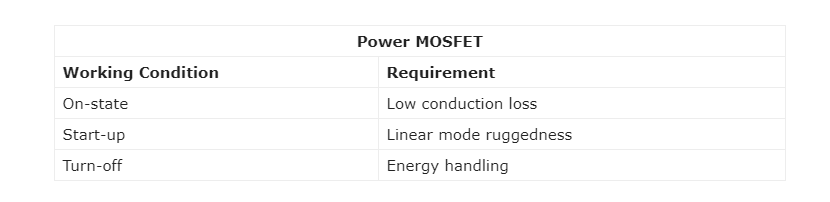
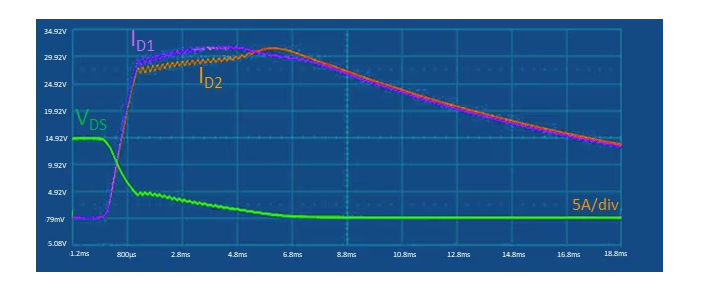
The threshold range of Vth is limited to a certain range (3%), so that the current difference between the two MOSFETs is small:


  • ID1 = 29A
  • ID2 = 28.5A

The value of Vth1 is low, so ID1  is slightly higher than ID2.


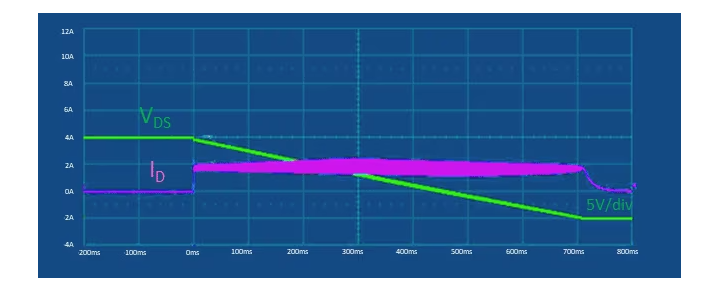
In this case (Case 2), the linear mode robustness of the power switch is tested with a high current, and the pulse time lasts for a few milliseconds.


In both cases, the power MOSFETs are able to withstand linear mode operating conditions and are within the theoretical safe working area (SOA) to prevent any thermal runaway of the device.


2.Off state

When switched off, the power MOSFETs must be subjected to enormous energy discharge stress. In fact, on the harness connecting the main battery to the end application control board, the parasitic stray inductance produces a high impedance, causing a powerful discharge event in the distribution system.


In the case of ECU, this energy release can be treated as a single avalanche event when the MOSFET is turned off, or an active clamping circuit can be used to force the MOSFET back to linear operating mode. TL325N4LF8AG can maintain normal operation in 40A avalanche breakdown test, as shown in Figure 5:


Figure 5. Measured waveform of STL325N4LF8AG for a single avalanche event at shutdown 

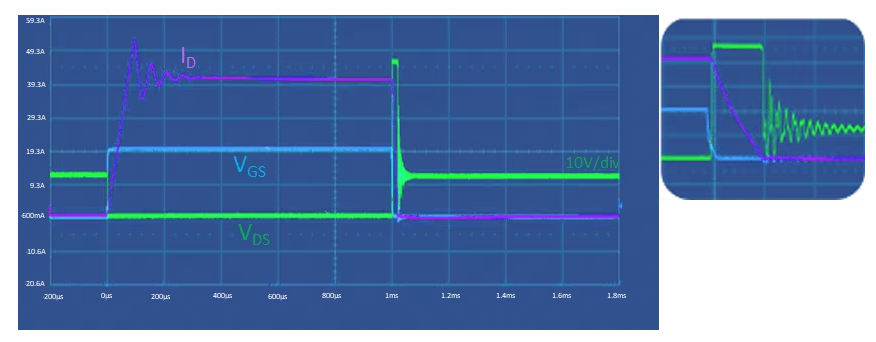
The device has strong energy handling performance in the off state.


According to ISO 7637-2

For 12V/24V automotive power supply systems, eFuse electronic safety switch tubes must meet the main requirements of the ISO 7637-2 international standard and be able to withstand the violent high and low power transient events generated on the power supply rail, in some cases with high dv/dt voltage rise rates.


1.ISO 7637-2 Pulse 1 standard

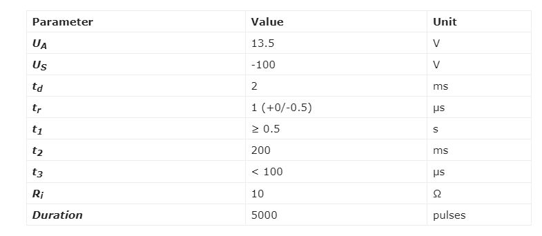
The Pulse 1 standard describes the negative voltage transients observed on electronic devices in parallel with inductive loads when the power connection is disconnected, as shown in Figure 6.


Figure 6. Voltage transient waveforms and parameters tested by ISO 7637-2 Pulse 1


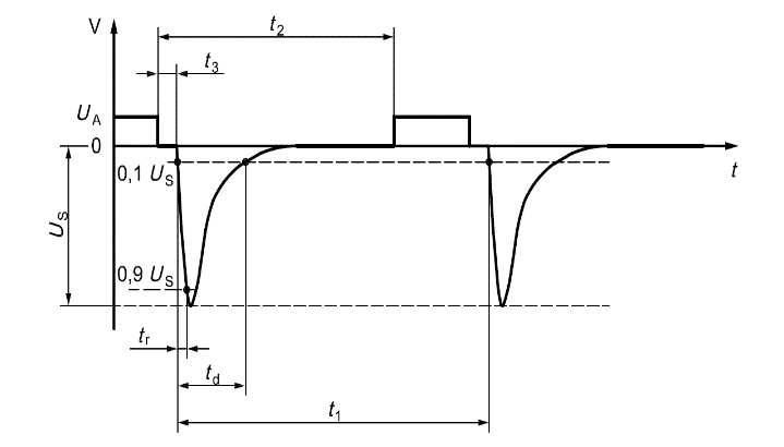
The test results shown in Figure 7 demonstrate that the STL325N4LF8AG meets the requirements of ISO 7637-2 Pulse 1:


Figure 7. Measurement waveform of the STL325N4LF8AG's ISO 7637-2 Pulse 1 test


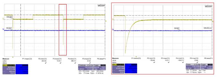
The experimental data show that the STL325N4LF8AG has passed the ISO 7637-2 pulse 1 test without any failure or reduction of main rated parameters.


2.ISO 7637-2 Pulse 2° standard

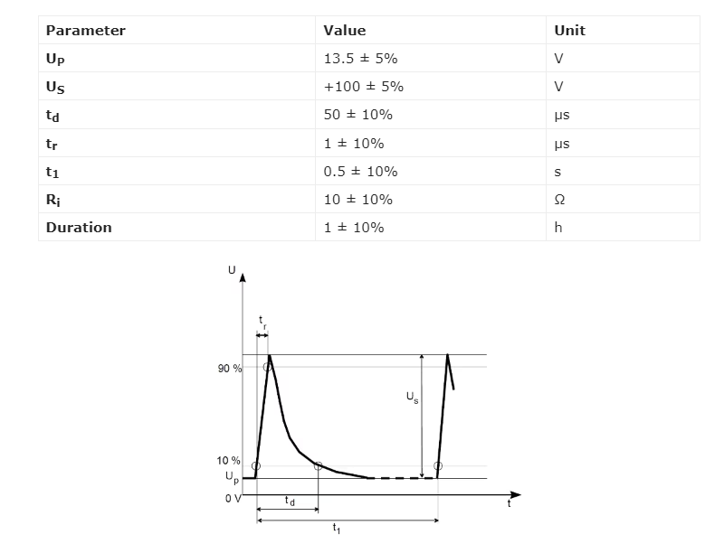
The Pulse 2a standard describes positive voltage spikes that may occur when the circuit current in parallel with the electronic device under test is interrupted, as shown in Figure 8: 


Figure 8. Voltage transient waveforms and parameters of the STL325N4LF8AG's ISO 7637-2 Pulse 2a test


The test results shown in Figure 9 demonstrate that the STL325N4LF8AG meets the requirements of ISO 7637-2 Pulse 2a:


Figure 9. Measurement waveform of the STL325N4LF8AG's ISO 7637-2 Pulse 2a test

            
The experimental data show that the STL325N4LF8AG has passed the ISO 7637-2 pulse 2a test without any failure or reduction of main rated parameters.


3.ISO 7637-2 Pulses 3a and 3b standards

Pulses 3a and 3b define the negative voltage spikes that may occur during the switching process due to the distributed capacitance and inductance of the harness, as shown in Figures 11 and 12:


Figure 10. Voltage transients for ISO 7637-2 pulse 3a test.


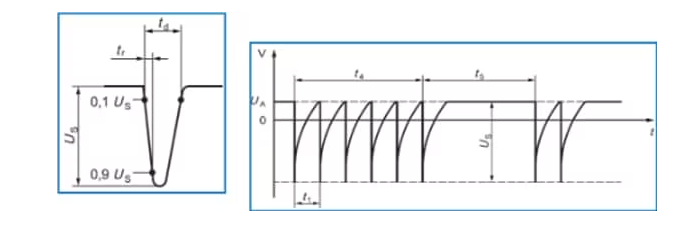
Figure 11. Voltage transients for ISO 7637-2 pulse 3b test


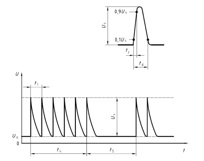
Table 2 lists the measured values of each parameter:


Table 2. Voltage transient parameters tested by ISO 7637-2 pulses 3a and 3b


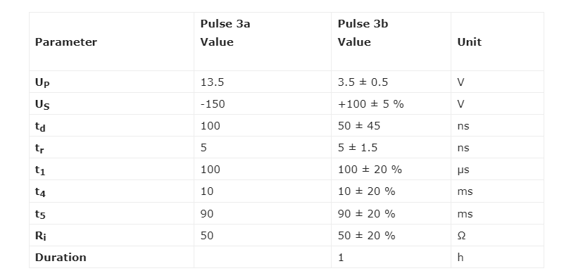
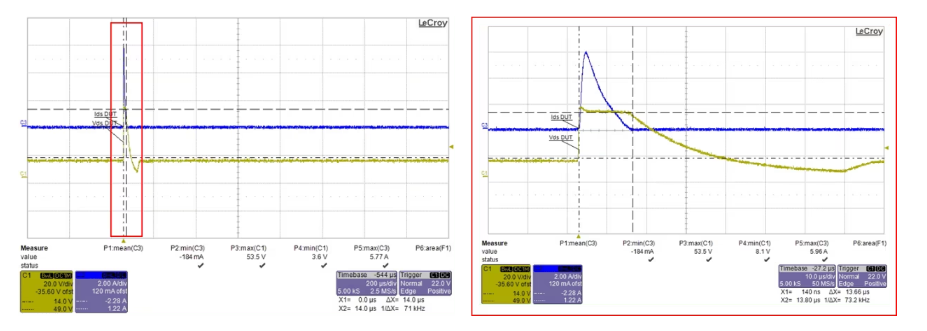
Figure 12 and 13 are the experimental data related to the ISO 7637-2 pulse 3a and pulse 3b tests of the STL325N4LF8AG:


Figure 12. Measurement waveform of the STL325N4LF8AG's ISO 7637-2 pulse 3a test


Figure 13. Measurement waveform of the STL325N4LF8AG's ISO 7637-2 pulse 3b test


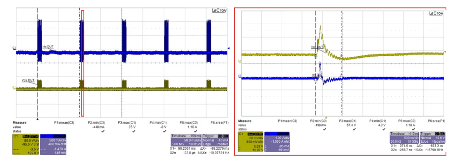
The pulse 3a and 3b test results of the STL325N4LF8AG are satisfactory.


4.ISO 7637-2 Pulses 5a and 5b (load drops)

Pulses 5a and 5b are simulated tests of load drop transients. Load drop refers to the situation where the discharge battery is disconnected while the other loads are still connected to the alternator during the period when the alternator is generating charging current, as shown in Figures 14 and 15:


Figure 14. Voltage transients for ISO 7637-2 pulse 5a test


Figure 15. Voltage transients for ISO 7637-2 pulse 5b test


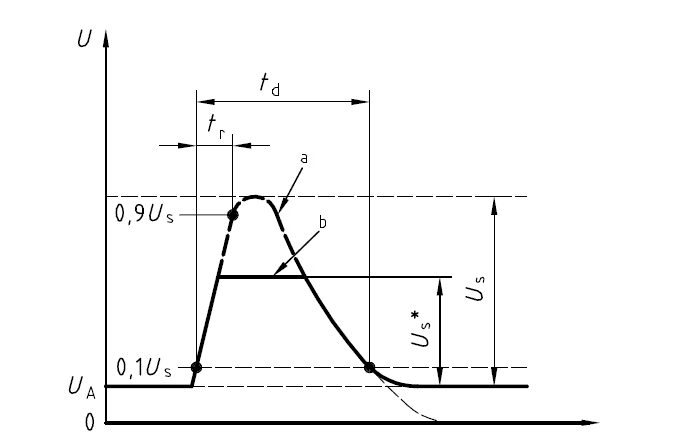
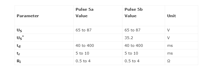
Table 3 lists the test parameter values of the 12V system:


Table 3. Voltage transient parameters tested by ISO 7637-2 pulses 5a and 5b


Figures 17 and 18 show the measurement waveforms for the STL325N4LF8AG's ISO 7637-2 pulse 5a and pulse 5b tests:


Figure 16. Measurement waveform of the STL325N4LF8AG's ISO 7637-2 pulse 5a test


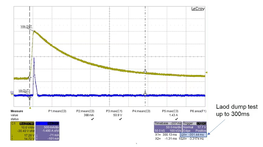
Figure 17. Measurement waveform of the STL325N4LF8AG's ISO 7637-2 pulse 5b test


Therefore, the STL325N4LF8AG can also provide load drop protection for the system


Conclusion

The STL325N4LF8AG uses ST's newly developed STripFET F8 manufacturing technology and is specifically designed to withstand all relevant voltage stress conditions for eFuse electronic insurance applications, both in power off and on states. In addition, the MOSFET has also passed the international standard ISO 7637-2 12V/24V automotive battery system on-transient test. The best-in-class performance makes the STL325N4LF8AG ideal for designing safer power distribution systems in harsh automotive applications.


Heisener Electronic is a famous international One Stop Purchasing Service Provider of Electronic Components. Based on  the concept of Customer-orientation and Innovation, a good process control system, professional management team,  advanced inventory management technology,  we can provide one-stop electronic component supporting services that Heisener is the preferred partner for all the  enterprises and research institutions.


Productos Relacionados