The IRG4PH50SPBF is a high-speed IGBT (Insulated Gate Bipolar Transistor) designed for switching applications. It features low conduction and switching losses, making it suitable for use in motor drives, inverters, and induction heating systems. With a maximum collector-emitter voltage of 1200V and a continuous collector current capability of 57A, it delivers efficient performance in high-voltage environments.
The IRG4PH50SPBF operates as an IGBT, combining the high input impedance of a MOSFET with the low saturation voltage of a bipolar transistor. When a voltage is applied to the gate, it allows current to flow from the collector to the emitter. Once turned on, it conducts efficiently with low losses. When the gate voltage is removed, it switches off and blocks high voltage across the collector-emitter terminals.
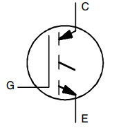
C (Collector): Main terminal for current input when the device is conducting.
G (Gate): Control terminal; applies voltage here to switch the device on or off.
E (Emitter): Current output terminal; connected to the circuit ground or load return path.
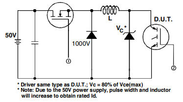
The Clamped Inductive Load Test Circuit is used for evaluating the switching performance of the IGBT device (D.U.T., Device Under Test), specifically the IRG4PH50SPBF. The circuit applies a 50V power supply to an inductive load, with a freewheeling diode and a clamp diode rated at 1000V to safely handle the voltage spike when the inductor discharges.
The driver transistor (same type as the D.U.T.) turns on to allow current to build in the inductor, and then turns off to force the inductor to release energy through the D.U.T., simulating real switching stress. This setup allows measurement of dynamic characteristics like turn-off energy and switching losses.
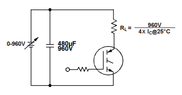
This Pulsed Collector Current Test Circuit is designed to evaluate the peak pulsed current capability of the IGBT (IRG4PH50SPBF). A high-voltage DC supply (0–960V) charges a 480 µF capacitor, which then discharges through the IGBT and a load resistor RLR_LRL. The value of RLR_LRL is set to ensure a pulse current equal to one-fourth of the IGBT’s rated collector current at 25°C. The gate is driven by a pulse signal, and the setup tests the IGBT’s ability to handle high current pulses without entering thermal or electrical breakdown.
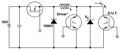
This is the switching loss test circuit for the IRG4PH50SPBF IGBT. The test setup includes a driver IGBT (②) that controls the switching of the device under test (D.U.T., ③). A DC voltage source (50V) charges the circuit, and an inductive load (L) stores energy. The freewheeling diodes across both the driver and D.U.T. prevent voltage overshoots. A high-voltage clamp (1000V) is included to protect the test circuit from overvoltage during switching events.
| Parameter | Value |
| Collector-Emitter Voltage (VCES) | 1200 V |
| Collector Current (IC) | 57 A |
| Pulsed Collector Current (ICM) | 114 A |
| Vce(on) (Max) @ Vge, Ic | 1.7V @ 15V, 33A |
| Gate-Emitter Voltage (VGE) | ±20 V |
| Power Dissipation (PD) | 200 W |
| Switching Energy | 1.8mJ (on), 19.6mJ (off) |
| Gate Charge | 167 nC |
| Td (on/off) @ 25°C | 32ns/845ns |
| Test Condition | 960V, 33A, 5Ohm, 15V |
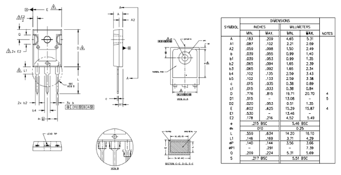
| Package Type | TO-247AC |
| Operating Temperature | -55°C ~ 150°C |
Standard: Optimized for minimum saturation voltage and low operating frequencies (<1kHz)
Generation 4 IGBT design provides tighter parameter distribution and higher efficiency than Generation 3
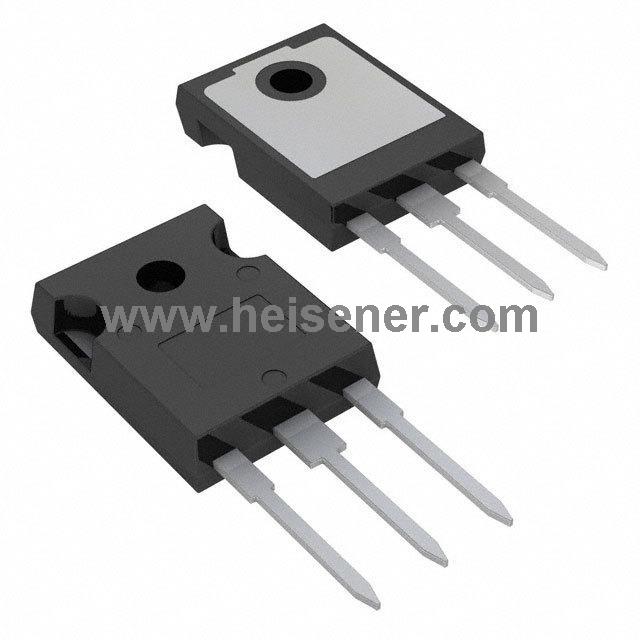
Industry standard TO-247AC package
Lead-Free
Generation 4 IGBT's offer highest efficiency available
IGBT's optimized for specified application conditions
Designed to be a "drop-in" replacement for equivalent industry-standard Generation 3 IR IGBT's
Motor drives (industrial AC motors, servo drives)
Inductive load switching (such as solenoids, coils)
High-frequency inverters and converters
Welding machines
Uninterruptible Power Supplies (UPS)
Switch-mode power supplies (SMPS)
Induction heating systems
EV charging stations and energy storage systems
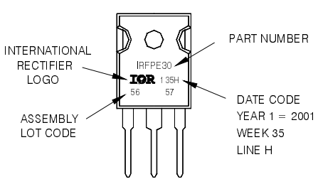
The IRG4PH50SPBF uses a TO-247AC package, which is a high-power, through-hole package designed for efficient heat dissipation and high current handling. It features three leads (Collector, Gate, Emitter) with a large mounting tab connected to the collector, ideal for mounting on heatsinks.
Datasheet PDF(https://dir.heisener.com/DatasheetDownload/IRG4PH50SPBF.pdf)
To connect the IRG4PH50SPBF, first identify its three terminals: Collector (C), Gate (G), and Emitter (E). The Emitter is typically connected to the ground or the negative terminal of the load. The Collector connects to the positive supply through the load, while the Gate receives the control signal from a gate driver or microcontroller. When a suitable voltage is applied to the Gate, the IGBT turns on, allowing current to flow from Collector to Emitter. Removing the gate signal turns it off, stopping current flow.
It is a 1200V Insulated Gate Bipolar Transistor (IGBT) designed for high voltage and high current applications.
Common alternatives include IGW30N65L5XKSA1, FGH25T120SMD-F155, and STGW25M120DF3.
It comes in a TO-247AC through-hole package, suitable for high power and effective heat dissipation.