IR2117 Introduction
The IR2117 is a high-voltage, high-speed driver used to control power MOSFETs and IGBTs (Insulated Gate Bipolar Transistors). It’s designed for rugged performance with its robust construction, utilizing proprietary technologies like HVIC (High-Voltage Integrated Circuit) and latch-immune CMOS, which make it reliable even in harsh conditions. The driver is compatible with standard CMOS logic signals, meaning it can easily interface with common control systems.
What makes the IR2117 stand out is its output stage, which includes a high-current pulse buffer that minimizes cross-conduction, preventing unwanted short circuits. This driver can drive both high-side and low-side N-channel power MOSFETs or IGBTs and can handle voltages up to 600V, making it suitable for a wide range of applications like motor control, power supplies, and inverters.
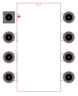
IR2117 Symbol

IR2117 Footprint
IR2117 3D Model

IR2117 Pinout

VCC: Logic and gate drive supply
IN: Logic input for gate driver output (HO), in phase with HO
COM: Logic ground
VB: High side floating supply
HO: High side gate drive output
VS: High side floating supply return
NC: No connection
IR2117 Typical Connection

IR2117 Functional Block Diagram

IR2117 Specification
| Specification | Value |
| Driven Configuration | High-Side |
| Supply Voltage | 10V ~ 20V |
| Logic Voltage - VIL, VIH | 6V, 9.5V |
| High Side Voltage(Max) | 600 V |
| Peak Output Current | 250mA(Source), 500mA(Sink) |
| Input Type | Non-Inverting |
| Supply Current | 2mA |
| Dead-Time | 500ns |
| Rise / Fall Time | 80ns, 40ns |
| Operating Temperature Range (Tj) | -40°C ~ 150°C |
| Package Options | 8-PDIP |
IR2117 Features
Floating channel designed for bootstrap operation
Fully operational to +600V
Tolerant to negative transient voltage
dV/dt immune
Gate drive supply ranges from 10 to 20V
Undervoltage lockout
CMOS Schmitt - triggered inputs with pull-down
Output in phase with input
Also available LEAD-FREE
IR2117 Applications
Motor Drives
Inverter Circuits
Switching Power Supplies
Induction Heating
Electric Vehicles (EVs)
Switch-Mode Power Supply (SMPS) Control
High-Frequency Switch-Mode Converters
Class-D Audio Amplifiers
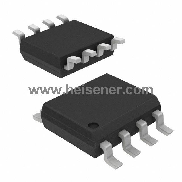
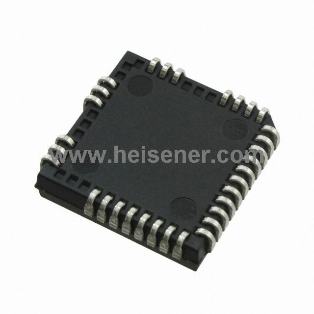
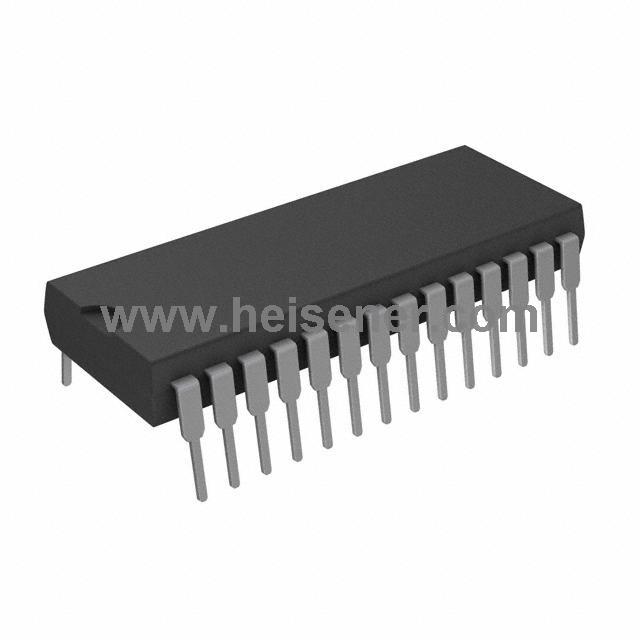
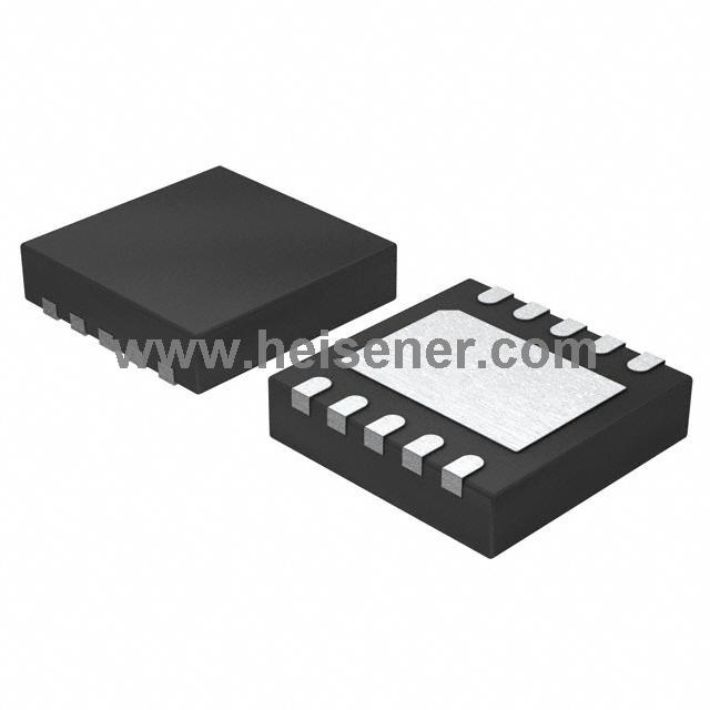
IR2117 Package
8 Lead PDIP is a widely used package for the IR2117 high-voltage MOSFET/IGBT driver. This package features a robust and easy-to-handle design with eight pins that connect to the driver’s logic input, output driver, and power MOSFET or IGBT control circuitry.
It is commonly used in applications such as motor drives, power supplies, and inverters. The package has dimensions of 9.81 mm in length, 6.35 mm in width, and a height of 4.57 mm, with a pin pitch of 2.54 mm, making it compact yet capable of providing reliable electrical performance.

How to Connect IR2117?
First, connect VCC to your logic supply and COM to the ground of your logic circuit. Then, for the high-side operation, connect VB to the bootstrap capacitor, which is charged through VS during operation.
Next, Connect the HO pin to the gate of the high-side MOSFET. For proper switching, apply a control signal to the IN pin. The IN pin controls the state of HO, turning the high-side MOSFET on or off based on the input logic level. Also, ensure the VS pin is properly referenced to the high-side MOSFET’s source.
Once everything is wired, make sure to include a bootstrap capacitor between VB and VS (typically 0.1µF) to provide the necessary voltage for high-side driving.
FAQs
What is IR2117?
The IR2117 is a high- and low-side driver designed for controlling power MOSFETs and IGBTs in motor drives, power inverters, and other applications where switching of high power is required. configuration.
How do I supply power to IR2117?
VCC provides the logic and low-side gate drive supply (typically 5V).
VB provides the high-side floating supply, which needs to be powered by a bootstrap capacitor when switching the high-side MOSFET.
COM is the ground reference for the low-side driver.
VS is the floating return for the high-side MOSFET source.
How do I protect the IR2117 during operation?
Use appropriate clamping diodes to prevent over-voltage.
Make sure the VS pin is connected to a proper voltage reference (high-side MOSFET source) for accurate operation.
Ensure that the VB pin is supplied with the proper bootstrap voltage via a capacitor.