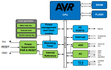
The ATTINY4-TSHR is a low-power 8-bit microcontroller built on Atmel’s enhanced AVR® RISC architecture. Designed for efficiency, it executes most instructions in a single clock cycle, delivering performance levels approaching 1 MIPS per MHz.
It has impressive processing capability to enable developers to strike an ideal balance between power consumption and speed, applying to power-sensitive embedded applications.
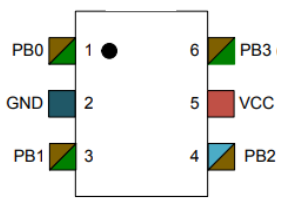
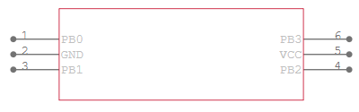
VCC: Digital supply voltage.
GND: Ground.
Port B (PB[3:0]): This is a 4-bit, bi-directional I/O port with internal pull-up resistors, individually selectable for each bit.
| Parameter | Description |
| Microcontroller Core | AVR® ATtiny 8-Bit |
| Operating Voltage | 1.8V ~ 5.5V |
| Program Memory (Flash) | 512B (256 x 16) |
| RAM | 32 x 8 |
| EEPROM | None |
| CPU Speed | 12 MHz |
| Performance | 1 MIPS per MHz |
| Number of I/O | 4 |
| ADC | None |
| Analog Comparator | 1 × Analog Comparator |
| Watchdog Timer | Yes |
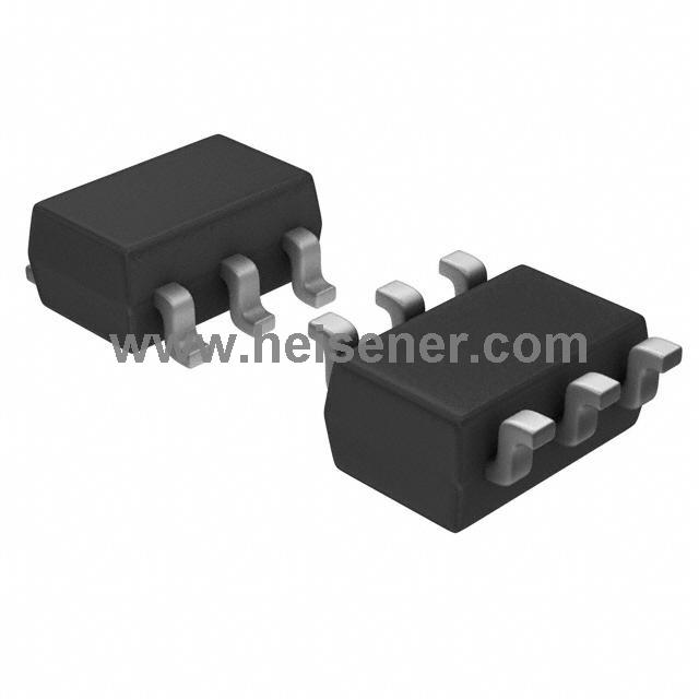
| Package Type | SOT-23-6 |
| Temperature Range | -40°C ~ 85°C |
High Performance, Low Power AVR®
8-Bit Microcontroller
Advanced RISC Architecture
Non-volatile Program and Data Memories
32 Bytes Internal SRAM
QTouch®
Library Support for Capacitive Touch Sensing (1 Channel)
In-System Programmable (at 5V, only)
External and Internal Interrupt Sources
Low Power Idle, ADC Noise Reduction, and Power-down Modes
Enhanced Power-on Reset Circuit
Industrial and Extended Temperature Ranges
Low Power Consumption
Battery-Powered Devices
LED Control Systems
Toys and Consumer Electronics
Timer-Based Applications
Signal Conditioning Circuits
Custom Logic Replacement
Education and Prototyping
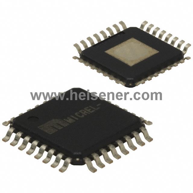
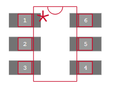
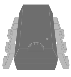
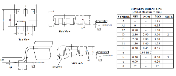
The ATTINY4-TSHR comes in a compact SOT-23-6 surface-mount package with just 6 pins. Despite its small size, it packs a punch—handling basic control, timing, and logic processing tasks with ease. The SOT-23-6 format also makes it easy to solder onto standard PCBs, making it an ideal choice for compact, portable devices or any application where board space is limited.
To test and connect the ATTINY4-TSHR, you’ll first need to set up a basic circuit on a breadboard or PCB. Start by connecting VCC to a regulated power supply, and GND to the ground rail. These two pins power the microcontroller. Then, connect a decoupling capacitor between VCC and GND, close to the chip, to reduce voltage ripple and noise.
Next, connect PB0 to PB3 depending on your intended I/O usage. For example, you can wire PB0 as an input to detect a button press by connecting one side of the button to PB0 and the other to GND, while enabling the internal pull-up in your code. If you're using PB1–PB3 as outputs, you can connect LEDs with current-limiting resistors to visualize signal states. During testing, you can flash a simple firmware using a compatible programmer (like a USBasp or Atmel-ICE) through the debug interface, typically using a 3-pin or 6-pin header wired to PB3 (RESET), VCC, and GND.
Once connected and powered, upload your program using AVR programming tools like AVRDude or Atmel Studio. You can test the chip by running basic tasks—like blinking an LED—to confirm proper connection and operation. Make sure to verify voltage levels and I/O responses with a multimeter or logic analyzer during testing.
The ATTINY4-TSHR is an ultra-compact 8-bit microcontroller from Microchip (formerly Atmel), based on the AVR® enhanced RISC architecture. It’s designed for simple control tasks with minimal power consumption and is ideal for cost-sensitive and space-constrained applications.
It has 4 bi-directional I/O pins: PB0, PB1, PB2, and PB3. These can be configured individually for input or output and come with internal pull-up resistors.
Common uses include LED control, simple timers, sensor interfacing, logic replacements, and compact automation tasks.