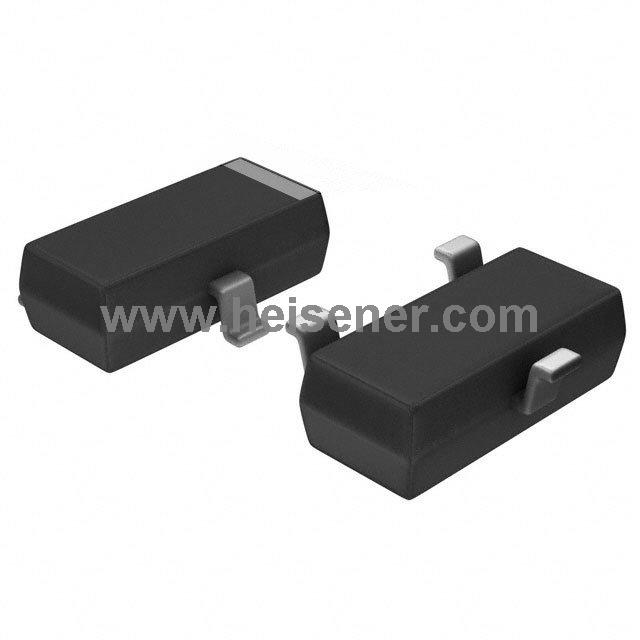
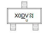
The AO3400A is a N-channel MOSFET that leverages advanced trench technology to deliver exceptionally low RDS(ON). Housed in a compact low-resistance SOT-23 package, it offers excellent switching characteristics, and it is ideal for space-constrained designs where thermal efficiency and fast response are critical.
This device is well-suited for use as a load switch in portable electronics or as a power driver in PWM (pulse-width modulation) applications, such as DC-DC converters or motor control circuits. Its combination of low gate charge, high-speed switching, and low on-resistance makes it a versatile choice for a wide range of low-voltage power management tasks.
The core working principle of the AO3400A is to control the flow of current between the drain and source terminals by adjusting the gate voltage. When the gate voltage exceeds a certain threshold relative to the source (typically above 2.5V), the MOSFET turns on, allowing current to flow from the drain to the source and completing the circuit. Conversely, when the gate voltage is below the threshold, the MOSFET turns off, blocking current flow and breaking the circuit.
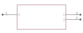
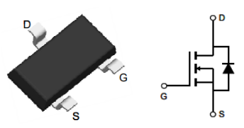
G (Gate) – The control pin that turns the MOSFET on or off.
S (Source) – The input/reference pin, typically connected to ground or the low-side of the circuit.
D (Drain) – The output pin, usually connected to the load or the high-side of the circuit.
| Parameter | Value |
| Type | N-Channel MOSFET |
| Drain-Source Voltage (Vds) | 30 V |
| Gate-Source Voltage (Vgs) | ±12V |
| Continuous Drain Current | 5.8A (Ta) |
| Drive Voltage (Max Rds On, Min Rds On) | 2.5V, 10V |
| Pulsed Drain Current | 20 A |
| Rds On (Max) @ Id, Vgs | 28mOhm @ 5.8A, 10V |
| Vgs(th) (Max) @ Id | 1.4V @ 250µA |
| Gate Charge (Qg) (Max) @ Vgs | 12 nC @ 4.5 V |
| Input Capacitance (Ciss) (Max) @ Vds | 1050 pF @ 15 V |
| Total Gate Charge (Qg) | 4.5 nC |
| Input Capacitance (Ciss) | 540 pF |
| Power Dissipation (Max) | 1.4W (Ta) |
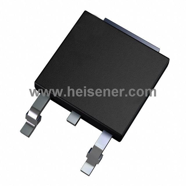
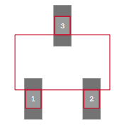
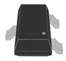
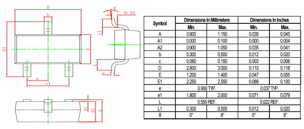
| Package | SOT-23 |
| Operating Temperature | -55°C ~ 150°C |
Low RDS(ON): Minimizes conduction loss and improves efficiency
High Current Handling: Supports continuous drain current
Low Gate Drive Requirement: Operates with logic-level gate voltages
Fast Switching Speed: Suitable for high-speed PWM applications
Small Form Factor: Compact SOT-23 package for space-saving designs
RoHS Compliant: Environmentally friendly and lead-free
Load Switches
Battery-Powered Devices
Power Management Systems
Motor Drivers
LED Drivers
USB Power Switches
The AO3400A adopts the SOT-23 package, a compact surface-mount form that offers advantages such as small size, good thermal performance, and suitability for automated SMT production. This package makes the AO3400A particularly ideal for use in portable devices, power modules, and embedded systems.
Datasheet PDF(https://dir.heisener.com/DatasheetDownload/AO3400A_101.pdf)
When testing the AO3400A, ensure it is properly connected to the test circuit. Connect the gate (G) to a voltage source capable of providing a voltage higher than the threshold voltage (usually above 2.5V), the source (S) to ground, and the drain (D) to the load or power source. When the gate voltage exceeds the threshold, the MOSFET will conduct, allowing current to flow between the drain and source; when the gate voltage is below the threshold, the MOSFET will turn off, blocking current flow.
When connecting the AO3400A, the gate should be connected to a control signal or PWM signal to switch the MOSFET on and off. The source (S) should be connected to ground, and the drain (D) should be connected to the load or power circuit, depending on the application. Ensure that the maximum drain-source voltage is not exceeded during operation, and provide adequate heat dissipation to maintain safe operating temperatures.
The AO3400A is commonly used in power management, load switching, and PWM applications, especially in portable devices, power modules, and embedded systems.
To test the AO3400A, connect the gate (G) to a voltage source above the threshold voltage, the source (S) to ground, and the drain (D) to a load. Measure the current flowing through the MOSFET when the gate voltage is above or below the threshold.
While the AO3400A is excellent for general load switching and power management, motor control applications may require a MOSFET with higher current handling capabilities.