Traction inverters are the main battery drain components in electric vehicles (EVs), with power levels up to 150kW or higher. The efficiency and performance of traction inverter directly affect the driving range of electric vehicle after a single charge. Therefore, in order to build the next generation of traction inverter systems, silicon carbide (SiC) field effect transistor (FET) is widely used in the industry to achieve higher reliability, efficiency and power density.
The isolated grid driver integrated circuit (IC) shown in Figure 1 provides electrical isolation from low voltage to high voltage (input to output), drives the high side and low side power modules of each phase of the inverter, and monitors and protects the inverter from various failures. According to the Automotive Safety Integrity Class (ASIL) functional safety requirements, grid driver ics must comply with ISO26262 standards, ensuring failure detection rates of ≥99% for single failure and ≥90% for potential failure.
In this article, we will focus on the technical advantages of real-time variable grid drive strength, a new feature that allows designers to optimize system parameters such as efficiency (which affects EV range) and SiC overkill (which affects reliability).
Figure 1: Block diagram of traction inverter for electric vehicle

Increased efficiency with real-time variable grid drive strength
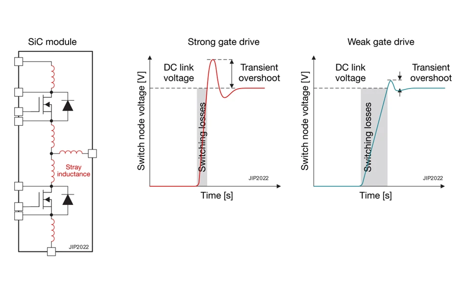
The grid driver IC must conduct the SiC FETs as efficiently as possible with as little switching loss as possible. The ability to control and vary the strength of the grid drive current reduces switching losses at the cost of increasing transient overshoot at switching nodes during switching. The switching speed of SiC can be controlled by changing the grid drive current, as shown in Figure 2.
Figure 2: SiC switching speed is controlled by changing the IC drive strength of the grid driver
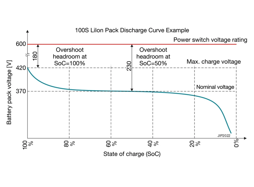
Real-time variable grid drive current enables transient overshoot management and design optimization of the entire high voltage battery energy cycle. A fully charged 100% to 80% charged battery should use a lower grid drive strength to keep SiC voltage overshoot within limits.As the battery power drops from 80% to 20%, the higher grid drive intensity reduces switching losses and improves traction inverter efficiency, which is the case for 75% of the charging cycle, so the improvement in system efficiency is significant. Figure 3 shows the typical transient overshoot in relation to the peak voltage and charge state of the battery.
Figure 3: Transient overshoot in relation to peak battery voltage and charge state
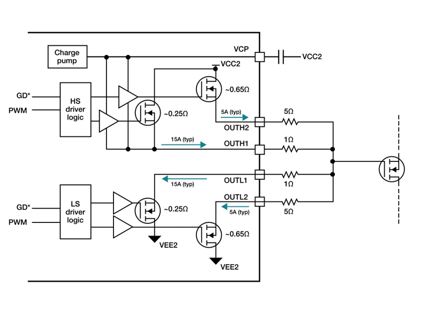
The UCC5880-Q1 is a maximum 20A SiC with multiple protection features suitable for traction inverters in automotive applications. Its gate drive strength is between 5A and 20A, and can be adjusted by a 4MHz bidirectional serial peripheral interface SPI bus or three digital input pins. Figure 4 shows the implementation of a dual separation output with variable grid drive intensity.
Figure 4: Dual output separate grid drive structure for UCC5880-Q1
Use DPT to evaluate power level switches
The standard method for evaluating the performance of power level switches in traction inverters is the double pulse test (DPT), which closes and disconnects SiC power switches at different currents. By changing the switching time, the SiC on and off waveforms under operating conditions can be controlled and measured to help evaluate efficiency and SiC overshoot, which can affect reliability. Figure 5 shows the connection diagram of a variable strength grid driver and SiC half-bridge with a UCC5880-Q1 low side DPT setup.
Figure 5: Low edge DPT block diagram

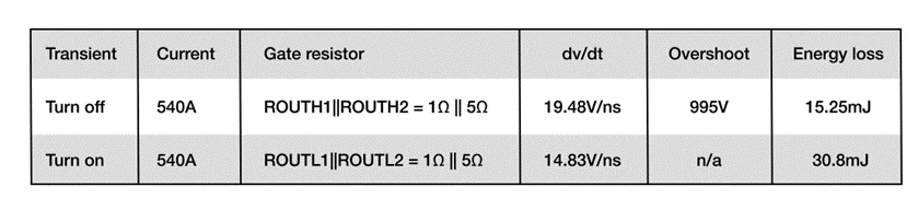
The results in Table 1 show how SiC with variable strength can help control overshoot while maximizing efficiency and optimizing thermal performance. EON and EOFF are switching energy loss respectively. VDS,MAX are the maximum voltage overshoot; TOFF and TON dv/dt are the switching speed of VDS during on and off respectively.

Relieve overshoot
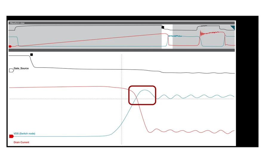
The waveform in Figure 6 shows the effect of variable grid drive strength on SiC overshot because the UCC5880-Q1 grid drive resistance and drive strength are controlled in real time. Power level overshoot is mitigated by using a lower grid drive (SiC off).
Figure 6: Effect of real-time variable grid drive strength on SiC overshoot: SiC strong drive shutdown (a); SiC weak drive off (b)
{a}
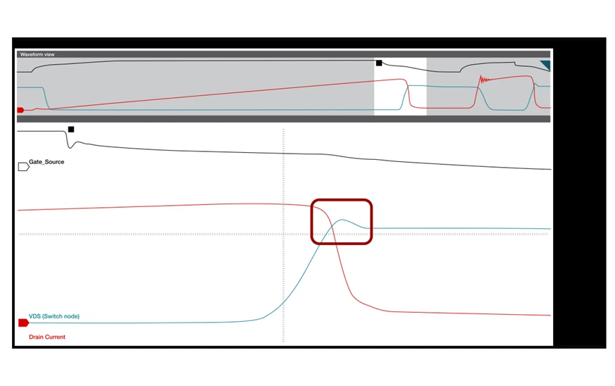
{b}
Table 2 lists the actual measurements used for comparison. Depending on the parasitic effects of the system and the noise control objectives, you can trade off between overshoot, dv/dt, and switching losses accordingly.
Extended driving range
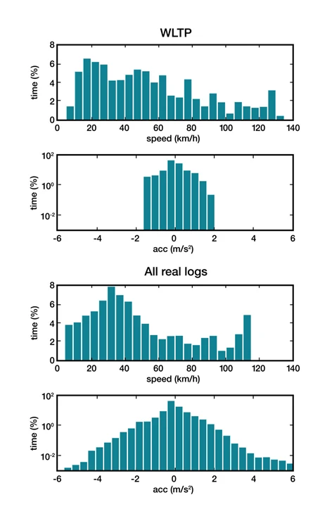
When using the powerful grid drive control features of the UCC5880-Q1 to reduce SiC switching losses, the efficiency gains can be significant, depending on the power level of the traction inverter. Modeling using the Global Uniform Light Vehicle Test Program (WLPT) and actual driving range speed and acceleration, as shown in Figure 7, shows that SiC power level efficiency gains of up to 2%, equivalent to an additional 11 km of range per battery. Those 11 kilometers could be the difference between consumers finding charging posts or getting stuck on the road.
Figure 7: WLPT and real range velocity and acceleration histograms
The UCC5880-Q1 also includes SiC threshold monitoring, which performs threshold voltage measurements each time the EV is pressed to start over the life of the system, and provides power switch data to the microcontroller for predicting power switch failures.
Conclusion
With electric vehicle traction inverters approaching 300kW power levels, there is an urgent need for greater reliability and greater efficiency. Selecting SiC with real-time variable grid drive strength helps to achieve this goal. The UCC5880-Q1 comes with design support tools, including an evaluation board, a user guide, and a functional safety manual, to assist you with your design.
| Nº de pieza | Descripción | |
|---|---|---|
| UCC5320ECDR Texas Instruments |
Aisladores - controladores de compuerta, ISO GATE DRIVER 3KV 8SOIC | RFQ |
| UCC5310MCDR Texas Instruments |
Aisladores - controladores de compuerta, ISO GATE DRIVER 3KV 8SOIC | RFQ |
| UCC5320SCD Texas Instruments |
Aisladores - controladores de compuerta, ISO GATE DRIVER 3KV 8SOIC | RFQ |
| UCC5320ECD Texas Instruments |
Aisladores - controladores de compuerta, ISO GATE DRIVER 3KV 8SOIC | RFQ |
| UCC5310MCD Texas Instruments |
Aisladores - controladores de compuerta, ISO GATE DRIVER 3KV 8SOIC | RFQ |
Traction inverters are the main battery drain components in electric vehicles (EVs), with power levels up to 150kW or higher. The efficiency and performance of traction inverter directly affect the driving range of electric vehicle after a single charge. Therefore, in order to build the next generation of traction inverter systems, silicon carbide (SiC) field effect transistor (FET) is widely used in the industry to achieve higher reliability, efficiency and power density.
Do you know the 8 application circuits of operational amplifiers?
This technical presentation requires an understanding of how to configure an operational amplifier in a typical gain control circuit. The applications of linear and nonlinear digital potentiometers are discussed. This article gives an overview of the basic techniques required to convert audio and other potentiometer/op amp applications from conventional mechanical potentiometers to solid state potentiometers
The current in an electronic circuit usually has to be limited. In USB ports, for example, excessive current must be prevented to provide reliable protection for the circuit. Also in the power bank, the battery must be prevented from discharging. Too high discharge current results in too large voltage drop of the battery and insufficient supply voltage of downstream devices
Using advanced real-time control technologies such as motor control circuits with higher power density, higher integration and more efficient systems, better acoustic performance of the system can be achieved
Brushless direct current (BLDC) motors have been widely used in household appliances, industrial equipment and automobiles. While brushless DC motors offer a more reliable and maintainable alternative to traditional brushless motors, they require more sophisticated electronics to drive them
How to achieve precise motion control in industrial actuators
The NCP51820 is a 650 V, high-speed, half-bridge driver capable of driving gallium nitride (" GaN ") power switches at dV/dt rates up to 200 V/ns. The full performance advantages of high voltage, high frequency and fast dV/dt edge rate switches can only be realized if the printed circuit board (PCB) can be properly designed to support this power switch. This paper will briefly introduce NCP51820 and the key points of PCB design of high performance GaN half bridge grid driver circuit using NCP51820