Condition monitoring is one of the core challenges of using mechanical facilities and technical systems today, such as using motors, generators and gears. Planned maintenance is becoming increasingly important to minimize the risk of production outages, not only in industry, but everywhere machines are used. In addition, the vibration mode of the machine is also analyzed. The vibration caused by the gearbox is usually perceived in the frequency domain as a multiple of the shaft velocity. Irregularities at different frequencies indicate worn, unbalanced, or loose parts. Accelerometers based on MEMS (micro-electromechanical systems) are commonly used to measure frequency. They have higher resolution, excellent drift and sensitivity characteristics, and better signal-to-noise ratio (SNR) than piezoelectric sensors. They can also detect low frequency vibrations close to the DC range.
This paper presents a high linear, low noise, broadband vibration measurement solution based on ADXL1002 MEMS accelerometer. The solution can be used for bearing analysis or engine monitoring, as well as all applications requiring a large dynamic range of up to ±50 g and a frequency response from DC to 11 kHz.
An example circuit is shown below. The analog output signal from the ADXL1002 is fed through the 2-pole RC filter to the Successive Approximation Register (SAR) analog-to-digital converter (ADC) AD4000, which converts the analog signal to a digital value for further signal processing.
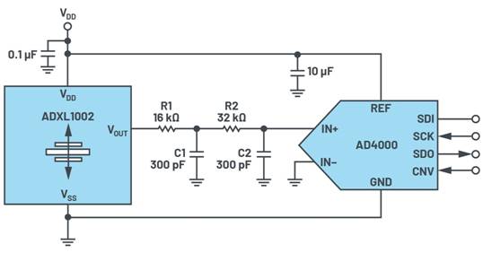
Example circuit for the ADXL1002
The ADXL1002 is a high-frequency, single-axis MEMS accelerometer that provides an output signal passband beyond the resonant frequency range of the sensor. This is needed so that frequencies beyond the 3 dB bandwidth can also be observed. For this purpose, the output amplifier of ADXL1002 supports a small signal bandwidth of 70 kHz. The output amplifier of the ADXL100 can also directly drive capacitive loads up to 1002 pF. For loads greater than 100 pF, 8 kΩ≥ series resistance should be used.
The ADXL1002 output requires an external filter to eliminate aliasing noise from the output amplifier and other internal noise components of the ADXL1002, for example, through the coupling of the internal 200 kHz clock signal. Therefore, the filter bandwidth should be implemented accordingly. Using the dimensions shown in Figure 1 (R1 = 16 kΩ, C1 = 300 pF, R2 = 32 kΩ and C2 = 300 pF), attenuation is approximately 200 dB at 84 kHz. In addition, the selected ADC sampling rate should be higher than the amplifier bandwidth (for example, 32 kHz).
For the ADC, the ADXL1002 supply voltage should be selected as the reference voltage source because the output amplifier is proportional to the supply voltage. In this case, the supply voltage tolerance and the voltage temperature coefficient (usually connected to an external voltage regulator) run between the accelerometer and the ADC, thus negating the implicit errors associated with the supply and reference voltage.
Frequency response
The frequency response of the accelerometer is the most important characteristic of the system, as shown in Figure 2. Gain increases above a frequency of about 2 kHz to 3 kHz. For the resonant frequency (11 kHz), the output voltage gain peaks at about 12 dB (coefficient 4).
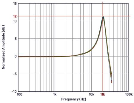
Frequency response of ADXL1002
To display the measured overrange, the ADXL1002 has an output (OR pin). The integrated monitor warns when a significant overrange event occurs.
Mechanical precautions for installation
Special care should be taken to place the accelerometer correctly. It should be mounted near a rigid mounting point on the board to avoid any vibration of the board itself and thus measurement error due to undamped board vibration. This position ensures that each circuit board on the accelerometer vibrates higher than the resonant frequency of the mechanical sensor, so that the accelerometer is barely visible. Multiple mounting points near the sensor and thicker circuit boards also help reduce the impact of system resonance on sensor performance.
Traction inverters are the main battery drain components in electric vehicles (EVs), with power levels up to 150kW or higher. The efficiency and performance of traction inverter directly affect the driving range of electric vehicle after a single charge. Therefore, in order to build the next generation of traction inverter systems, silicon carbide (SiC) field effect transistor (FET) is widely used in the industry to achieve higher reliability, efficiency and power density.
Do you know the 8 application circuits of operational amplifiers?
This technical presentation requires an understanding of how to configure an operational amplifier in a typical gain control circuit. The applications of linear and nonlinear digital potentiometers are discussed. This article gives an overview of the basic techniques required to convert audio and other potentiometer/op amp applications from conventional mechanical potentiometers to solid state potentiometers
The current in an electronic circuit usually has to be limited. In USB ports, for example, excessive current must be prevented to provide reliable protection for the circuit. Also in the power bank, the battery must be prevented from discharging. Too high discharge current results in too large voltage drop of the battery and insufficient supply voltage of downstream devices
Using advanced real-time control technologies such as motor control circuits with higher power density, higher integration and more efficient systems, better acoustic performance of the system can be achieved
Brushless direct current (BLDC) motors have been widely used in household appliances, industrial equipment and automobiles. While brushless DC motors offer a more reliable and maintainable alternative to traditional brushless motors, they require more sophisticated electronics to drive them
How to achieve precise motion control in industrial actuators
The NCP51820 is a 650 V, high-speed, half-bridge driver capable of driving gallium nitride (" GaN ") power switches at dV/dt rates up to 200 V/ns. The full performance advantages of high voltage, high frequency and fast dV/dt edge rate switches can only be realized if the printed circuit board (PCB) can be properly designed to support this power switch. This paper will briefly introduce NCP51820 and the key points of PCB design of high performance GaN half bridge grid driver circuit using NCP51820